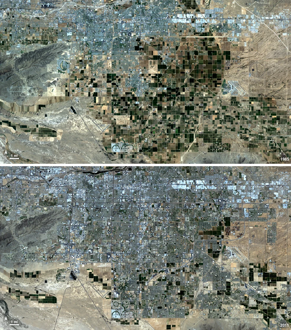
Begin with the decision and the observable target
The practical question is: Which planted areas intersect observed inundation during a specific flood episode? Work with flood-exposed crop parcels as the reporting unit and define the observation period before choosing an image or algorithm. Radar and cloud-free optical observations can map water-related changes, while crop calendars establish which parcels were planted at the relevant time.
Agricultural monitoring works best when the observation unit matches the decision unit. A farmer operates a field, irrigation block or management zone, not an isolated image pixel. Maintain planting dates, crop identity, harvested area and management history in a separate register, then connect the image measurements through stable identifiers. These records explain why neighboring green surfaces may represent different production stages. Before comparing farms, agree on the season definition and the denominator used for every percentage. An area with no usable observation must not silently become bare land, failed crop or normal condition. Review whether the target is large enough for the chosen pixels; field-edge mixtures become especially important in smallholder mosaics. Where the question depends on crop identity, nutrient status, water stress or final production, ask what independent measurement could distinguish competing explanations. The satellite layer should direct that measurement and preserve its outcome. This creates a useful operational record rather than an unexplained color ranking.
Select observations with suitable physical and temporal support
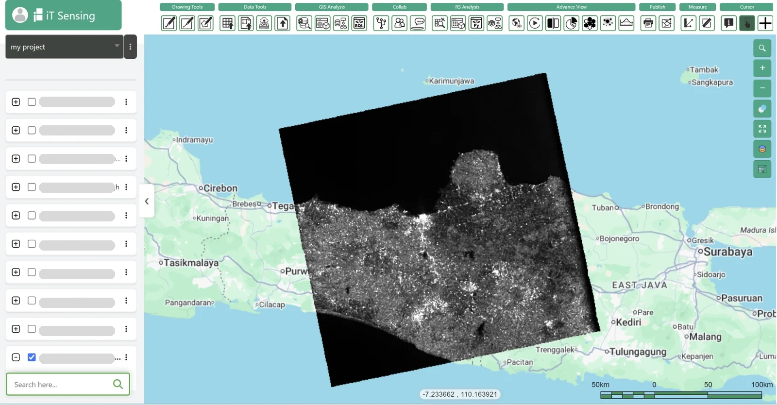
Radar provides active microwave observations and can acquire data without sunlight through cloud conditions that limit optical imagery. This advantage does not remove geometric and physical interpretation problems. Choose a compatible acquisition mode, polarization, orbit direction and processing level for the task. Backscatter intensity, coherence and interferometric phase contain different information and require different workflows. Terrain correction, incidence angle, speckle and layover or shadow can materially affect a result. A smooth dark radar surface is not universally water, and a low-coherence area is not universally damage. Examine known stable examples and relevant land-cover contexts before choosing thresholds. Maintain acquisition geometry and quality information in the project record. For interferometry, use dedicated processing with documented references and independent validation; a general raster analysis interface alone does not establish that an operational interferometric chain has been implemented or evaluated.
Build a compact data manifest before processing. Record the area of interest, acquisition times, product identifiers, processing versions, bands or variables, units, scale factors and quality criteria. Check the actual usable coverage over the target rather than relying only on scene-wide quality percentages. Preserve the original masks and define how missing values propagate into derived layers. If several dates or sensors are combined, keep their support information available in the project. These details make it possible to repeat a measurement and to explain why a later run changes after a product revision. They also help a colleague decide whether an apparent disagreement comes from the environment, the observation conditions or a processing choice.
Build an analysis rule that can be reviewed
Map the event’s observed extent, distinguish normal water and intersect a dated crop layer. Preserve uncertainty at field edges and explicitly report acquisition timing.
Exposure analysis overlays an observed or modeled process with assets that have their own dates and positional uncertainty. Confirm whether the process layer describes an actual event, a scenario or a probability surface; these should not share an unlabeled total. Check asset completeness, duplicate identifiers and the meaning of any population or value attributes. Small positional errors can change which side of a boundary an asset occupies, so test appropriate intersection tolerances and preserve boundary cases. An exposed asset is not automatically damaged or nonfunctional. Keep consequence assessments in separate fields linked to independent evidence. Summaries should identify the common analysis area, missing assets and unobserved process zones. This makes the resulting register auditable and prevents a simple spatial join from being mistaken for a complete impact assessment.
Start with a small, independently reviewed subset before applying the rule across the full geography. Inspect inputs and intermediate layers at both overview and local scales, checking that units, masks and coordinate alignment behave as intended. Keep a named version of the analysis configuration and retain a concise explanation of every consequential threshold. When the workflow moves to another region or season, revisit those assumptions instead of assuming that successful execution proves scientific transfer. A repeatable pipeline is valuable because its choices can be inspected and revised, not because automation makes the interpretation automatically correct.
Interpret the result without hiding alternative explanations
Flood exposure does not equal plant mortality or economic loss. Canopy-covered flooding and short-lived events may be missed.
Keep the target interpretation distinct from the evidence used to support it. For flood-exposed crop parcels, ask whether the observed pattern persists under a reasonable alternative baseline, quality mask or aggregation. Review apparent successes and plausible counterexamples together. If competing explanations cannot be separated with the available observations, record the finding as a candidate for investigation. This preserves useful spatial information while showing exactly which part of the conclusion still depends on independent evidence. The next observation should be chosen to resolve that uncertainty, rather than simply to reproduce a similar-looking map.
Validate with independent evidence before scaling
Check water marks, gauge timing and crop-condition inspections after access returns.
Check the geometry and assumptions that drive the spatial conclusion. Validate a representative sample of boundaries, links and asset positions with independent sources appropriate to their scale. Compare outputs under plausible changes to buffers, thresholds or network rules, then identify locations whose classification is sensitive. Retain unresolved links and boundary cases instead of silently choosing the alternative that produces a cleaner map. Field observations should test the proposed physical or operational relationship, such as an actual drainage connection or a usable public entrance. If the result is a planning scenario, evaluate whether its criteria match the decision-makers’ needs without claiming the ranking is an observed truth. Keep the independently verified attributes distinguishable from the modeled spatial relationships in the delivered dataset.
Deliver a usable GIS evidence layer
Deliver crop exposure estimates separately from subsequent field-assessed damage.
For GIS delivery, retain stable feature identifiers, source observation dates, the physical variable, units, valid support area, uncertainty and review status. Use a suitable coordinate reference for any area or distance calculation and document the transformation when joining outside layers. Separate measured or observed attributes from modeled and field-confirmed attributes so users can update one evidence type without overwriting the others. Include an unknown or unsupported state in summaries and preserve the denominator used for percentages. A map legend, concise data dictionary and accessible source links make the result useful to colleagues who did not run the analysis. Export formats should match the actual downstream workflow, with attribute encoding and geometry checked before handoff.
Turn the method into a practical iT Sensing workflow
iT Sensing brings satellite discovery, raster analysis, machine learning, GeoAI, visual model workflows and Python experimentation into a cloud remote sensing workspace. Use its documented tools to organize the inputs, test appropriate raster operations and connect evaluated results to a project-aware GIS workflow. The existence of a general tool does not guarantee that every specialist retrieval described here is available as a ready-made operation. Check the documentation and, where necessary, bring independently processed and evaluated products into the project with their provenance intact. A practical next step is to test the workflow on a representative area, review the evidence with domain specialists and choose the workspace plan that fits the team’s real storage, collaboration and processing needs.